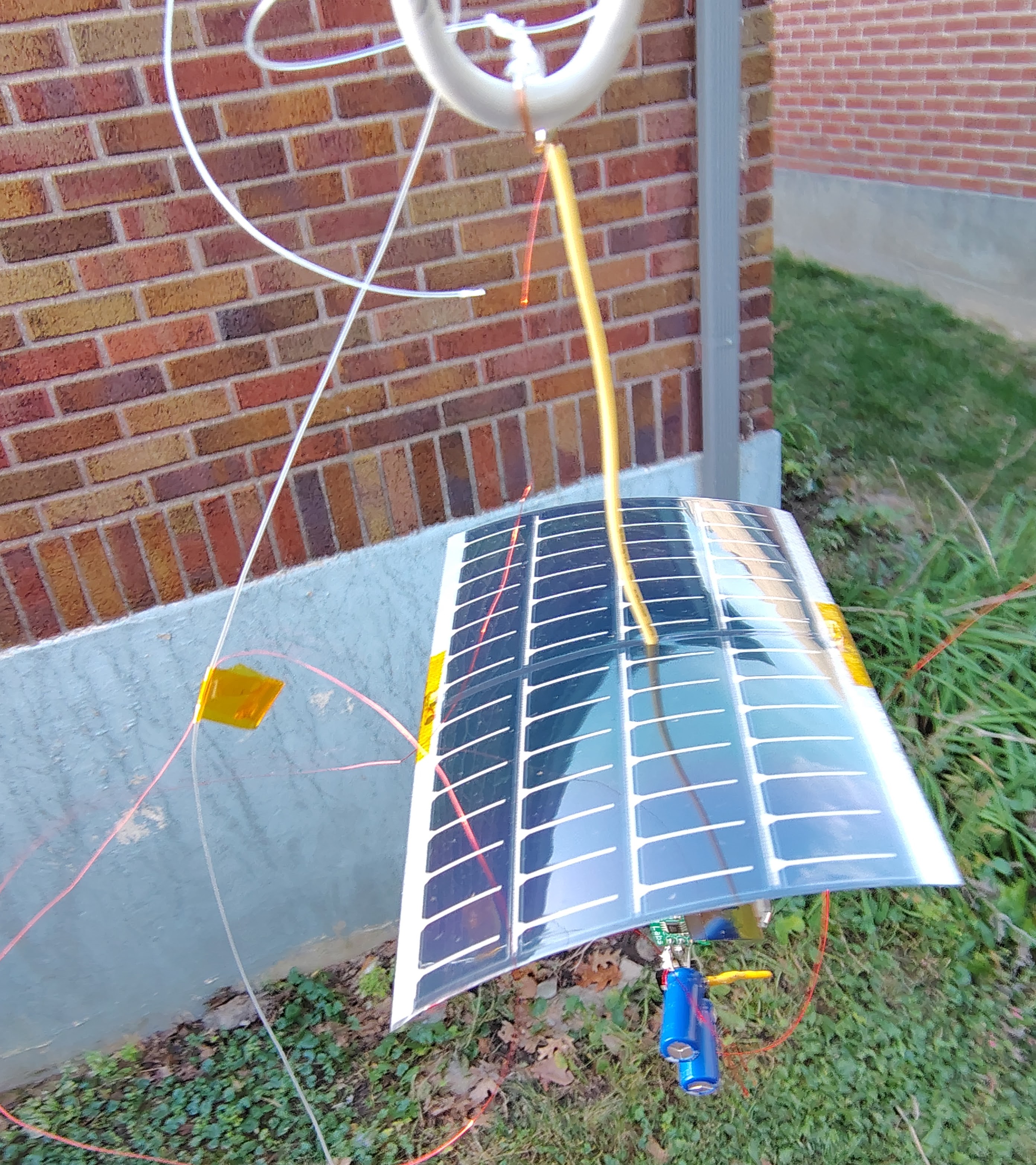
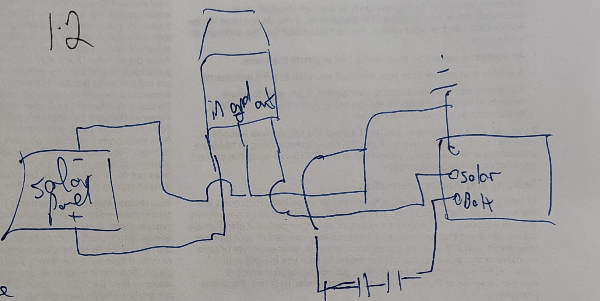
This is the power supply circuit for the smore-002 ballon. The tracker is a QRP-labs U4B S/N: 21894, only showed partially here. The solar panel can put out 6.8 Volts which is too much for the U4B so I used a regulator to that down to 5 Volts. I had some Kyocera AVX 3V 3.3 Farad super caps so I used two in series connected to the battery terminal.
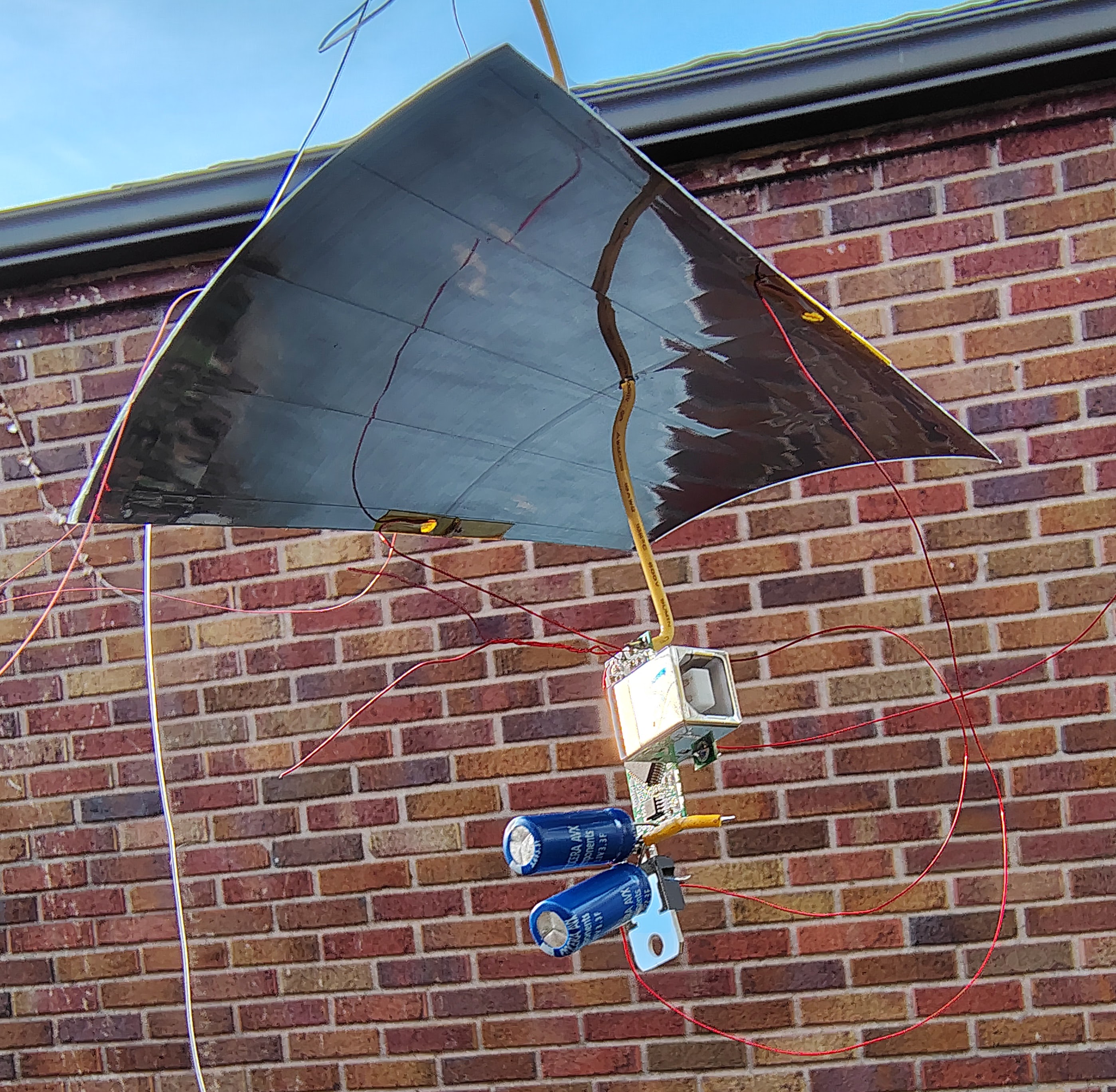
These solar panels have an inactive region in the middle and they can actually be cut in half. I punched a hold through this region and ran a stiff copper wire through the hole. This wire forms part of the upper half of the HF dipole antenna and provides an attachment point for the fishing line that forms the rigging to the balloon.
One advantage of this design is that the ground tab on the voltage regulator makes a great place to attach a clip for measureing voltage during testing and just before launch to verify power from the solar panel.
One disadvantage is that there is no way to inject power into this circuit safely. A Schottky diode should be used in the future to protect the solar panel and allow injection of external power for testing after dark.
The upper half of the antenna starts off with solid core stiff wire that penetrates the solar panel. This is soldered to a thin 34 AWG wire which forms the remainder of this antenna. The 34 AWG wire is glued loosely (with Elmers) to fishing line that forms the structural support and attached to the balloon.
Parts and weights
Parts and weights used for tracker design. Not including GPS antenna/solder/etc. Total weight came to 16.7 grams.
Solar panel is regulated with a L7805A (ST Microelectronics, n.d.) which is a 5 V version. This is probably not the best choice since the solar panel probably was under volting this value under limited light conditions.
Efficiency unknown.
Should be tested with full range of voltage in future.
Test the regulator on the bench. At 4.8V input to the regulator, output is 3.8V, with no load.
Here’s a measured table
V_in
V_out
7.4
4.9
7.0
4.9
6.8
4.9
6.4
4.9
5.0
4.0
4.8
3.8
4.7
3.7
4.5
3.5
4.4
3.4
4.3
3.3
4.2
3.3
4.1
3.2
4.0
3.1
During ground testing, I was trying to test outside during a cloudy day and attempted to provide power via a battery pack to the “battery” terminals of the U4b, also the +/- terminals of the series super capacitors. This didn’t work because current flowed back into the regulator and I could not get enough voltage to turn the U4b on. Further testing revealed that the regulator was not damaged by this, but I learned that a diode may be required to allow a battery hookup like this for testing the payload in the future.
Super capacitor
Used two Kyocera AVX 3.0V 3F supercapacitors (Kyocera, n.d.) in series, connected to the U4b’s battery connection. With the 5V regulator when fully charged, provides total energy storage \(E\)
\[\begin{equation}
E = \frac{1}{2} C \left[V_{max}^2 - V_{min}^2 \right]
\end{equation}\] with capacitance \(C\) and voltages between \(V_{max}\) and \(V_{min}\).
empirically runs to about 2.2 V then stops using self test mode from USB CLI
in sleep mode LED stays on until about 2.2 V then goes out
Using Sabrent USB hub with mechanical switches, these only switch the power lines if super caps are used to power the U4b, you can power up the U4b in USB mode, charge the super caps and then disconnect the switch, while maintaining a USB data connection to the host computer. You can then power the U4b externally.
---title: Payload design---## Introduction## Power circuitThis is the power supply circuit for the smore-002 ballon. The tracker is a QRP-labs U4B S/N: 21894, only showed partially here. The solar panel can put out 6.8 Volts which is too much for the U4B so I used a regulator to that down to 5 Volts. I had some Kyocera AVX 3V 3.3 Farad super caps so I used two in series connected to the battery terminal.These solar panels have an inactive region in the middle and they can actually be cut in half. I punched a hold through this region and ran a stiff copper wire through the hole. This wire forms part of the upper half of the HF dipole antenna and provides an attachment point for the fishing line that forms the rigging to the balloon.One advantage of this design is that the ground tab on the voltage regulator makes a great place to attach a clip for measureing voltage during testing and just before launch to verify power from the solar panel. One disadvantage is that there is no way to inject power into this circuit safely. A Schottky diode should be used in the future to protect the solar panel and allow injection of external power for testing after dark. - [QRP-Labs U4B](https://qrp-labs.com/u4b) - [Hardware manual](/_sources/u4b/u4b_hardware.pdf) - [Software v1.00.005 manual](/_source/u4b/u4b_operation_1_00_005.pdf)- [Powerfilm MPT48-150](/_datasheets/powerfilm_onp1237x54_apr22_xonlink.pdf)- [Kyocera AVX 3V supercapacitors](/_datasheets/AVX_SCC_3_0V-2952762.pdf)- [ST L7805CV voltage regulator](/_datasheets/L7805CV_voltage_regulator.pdf)## HF antennaThe upper half of the antenna starts off with solid core stiff wire that penetrates the solar panel. This is soldered to a thin 34 AWG wire which forms the remainder of this antenna. The 34 AWG wire is glued loosely (with Elmers) to fishing line that forms the structural support and attached to the balloon.## Parts and weights| Part | no | weight ||----------------------------------|---:|-------:|| Powerfilm MPT48-150 | 1 | 3.8 || supercap AVX_SCC_3_0V-2952762 | 2 | 2.4 || volt regulator L7805CV | 1 | 1.7 || u4b (with usb) | 1 | 5.4 || u4b (without usb) | 1 | 1.8 || upper HF antenna + rigging | 1 | 4.1 || lower HF antenna | 1 | 0.9 || TOTAL | | 14.2 |: Parts and weights used for tracker design. Not including GPS antenna/solder/etc. Total weight came to 16.7 grams.{{< include /_sources/power/budget.qmd >}}## References:::{#refs}:::