Fourth Launch s’more-003
First balloon with 3-solar panel design. Replaced regulator with Zener diode to reduce weight. This power design worked down to about 10 deg sun elevation. Spots received consistently throughout flight.
Balloon went above the Arctic circle and came down near Baffin Island, Canada probably in a storm.
The new 3 solar panel design was meant to allow operation at lower sun elevations and suceeded allowing operation down to nearly 10 degrees solar elevation. The voltage regulator was replaced with a zener diode which reduced the weight of the payload.
Tracking information
Payload at launch
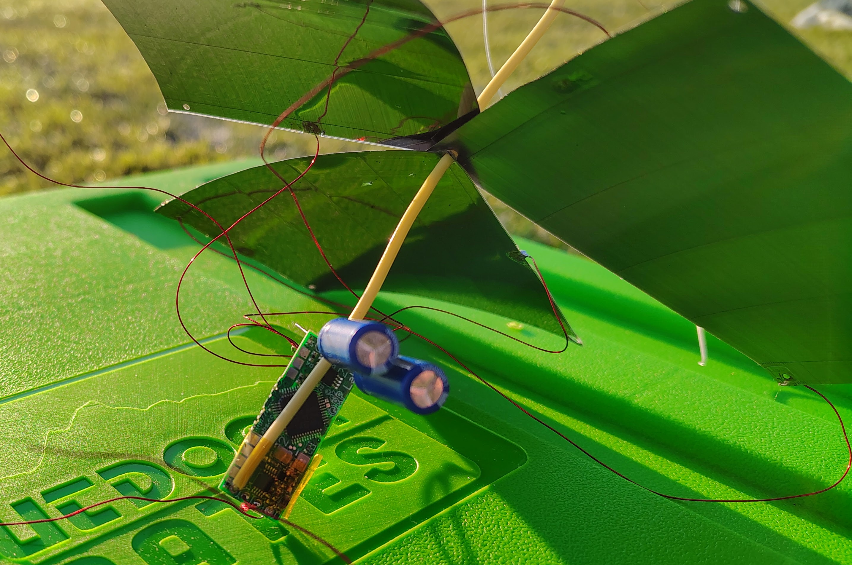
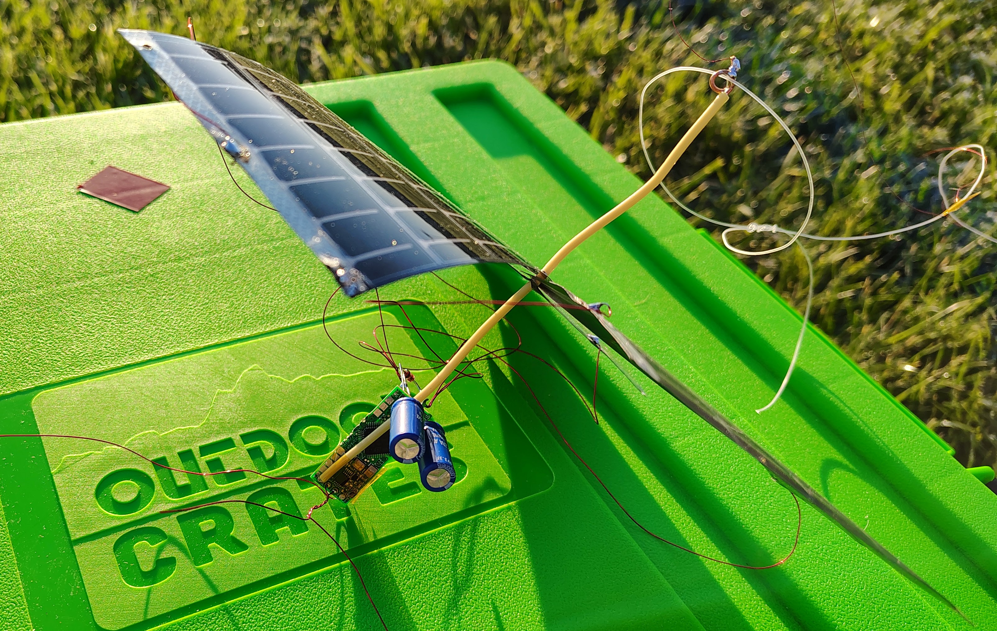
Pre-launch design and preparations
- u4b tracker
- zener diode regulation
- supercaps x2
- 3 half solar panels
- schottkey diodes
- HF antenna - 20m band
- GPS antenna
- 2 balloons
- WSPR channel selection
- planning channel 567, 2 minutes after, 14,097,060 MHz
- registered in QRP-labs database as smore-003 [2026-02-08]
- tried to register in traquito system, but doesn’t work [2026-02-08]
Payload weight
- USB connector removed from U4B.
- With antenna winders: 31.7 gram.
- Antenna winder 1 (bottom): 6.2 gram
- Bottom antenna + winder: 8.5 g (200 inches wire)
- Antenna winder 2 (top): 6.2 gram
- Bottom antenna + winder: 10 gram (200 inches wire + fish line)
- Total antenna winder: 15 gram
- Payload weight: 16.7 gram
Balloon filling calculations
Launch checklist
Pre-launch
At launch site
Testing
2025-10-16
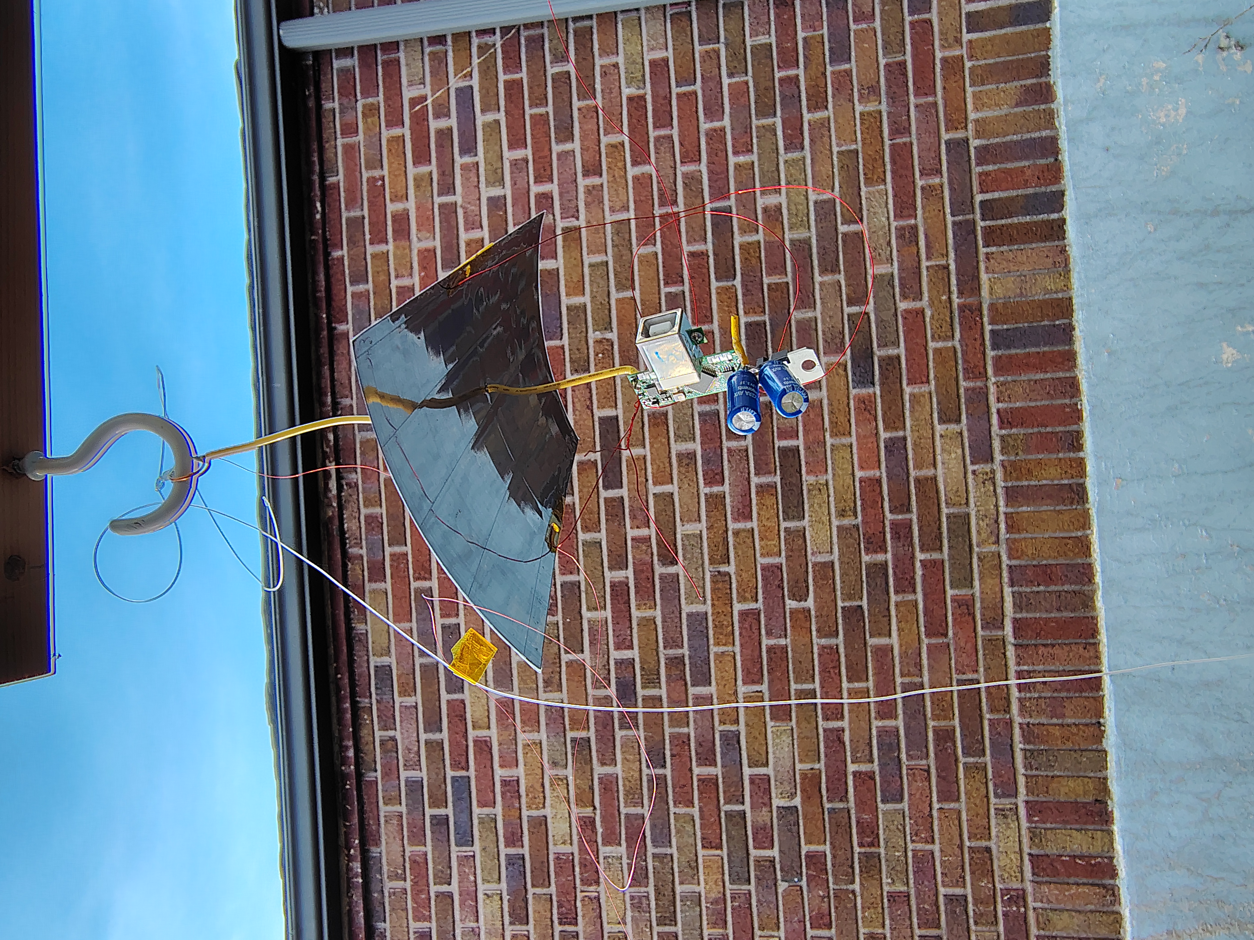
Set up balloon payload on wooden poles with horizontal wiring in morning of 2025-10-16 and let it start with sunrise.
wspr.rocks spots
Downloaded spot from https://wspr.rocks in both json and tsv format for comparison.
These are the spots from one day of testing 2025-10-16 local time 2025-10-16-wpsr-rocks-spots.json 2025-10-16-wpsr-rocks-spots.tsv
lu7aa spots
https://lu7aa.org.ar/wsprx.asp?banda=All&other=KF8EEZ&balloonid=×lot=&SSID=&launch=&tracker=qrplabs
csv file created by copy/paste from website
2025-10-16-lu7aa-spots.csv
this shows decoded telemetry also https://lu7aa.org/wsprx.asp?banda=20m&other=kf8eez&balloonid=05×lot=8&repito=on&qrpid=109&SSID=11&launch=20251016010101&tracker=qrplabs
wsprtv.com
shows charts https://wsprtv.com/?cs=kf8eez&ch=109&band=20m&start_date=2025-09-17
downloaded csv to KF8EEZ_109_20250917-20251017.cs
power down
Solar panel ends in shadow early due to trees.
Let up over night to allow to start again with sunrise.
2025-10-17
Came back up after overnight testing and starting transmitting. Brought inside due to forecast rain overnight.
2025-10-20
Additonal testing. Working in sun.
2025-10-23
Broke off the USB connector from the U4B and mounted again outside for testing. Partly cloudy but transmitted fine during sun.
Payload design
New payload design with 3 solar panels and zener diode.
U4B and programming information
Configuration
Firmware: 1.00.005 (make sure to upgrade to this version)
Callsign: KF8EEZ
Band: 20m
Channel: 567
- 2 minutes after, 14,097,060 MHz
Autostart: TRACKER2
QRP-labs S/N: 21811
zener diode as regulator, 3, 1/2 panels to provide voltage
mass: 16.9 gram including u4b-usb connector.
HF antenna
for top antenna leg, attached wire to fishing line with kapton tape, small piece about every 12 - 18 inches apart. Cut off small folded over ends with sticky tab.
Programs
Variables
- C is the count of transmissions since wake up
- N is the number of transmissions before switching to high-power (0-based)
- T is a flag for test mode
- T=1 - test mode
- T=0 - live mode - must be in live mode for flight
- B is the number of times to blink the led, set to 5
TRACKER2
This is the primary program. The MYTELE and MYGPS subroutines enable control of a test mode which doesn’t need GPS or ability to transmit.
PRINT "START TRACKER2"
RUN "INIT"
RUN "SHOW"
LET B = 5
RUN "BLINK"
PRINT "INITIAL GPS"
RUN "MYGPS"
LET B = 2
RUN "BLINK"
10 PRINT "LOOP AT #VC"
RUN "SHOW"
RUN "MYTELE"
LET C = C + 1
IF C > N
    LET HP = 1
ENDIF
RUN "MYGPS"
GOTO 10
INIT
Initialization should run once on power up.
PRINT "INIT START"
LET CH = 567
LET HP = 0
LET C = 0
LET N = 2
LET T = 1
LET B = 5
PRINT "HOST USB:    #US"
PRINT "HIGH POWER:  #HP"
PRINT "FREQUENCY:   #FQ"
PRINT "CHANNEL:     #CH"
PRINT "CALLSIGN:    #CS"
PRINT "TEMPERATURE: #TK"
IF T = 1
PRINT "FAKE GPS/TELE MODE"
ELSE
PRINT "REAL GPS/TELE MODE"
ENDIF
PRINT "INIT DONE"
SHOW
Prints out the current state
PRINT "SHOW START"
PRINT "LLH:  #LT #LN #AT"
PRINT "GPS:  VALID: #GV LOCK: #GL SPEED: #GS CALIB: #CL"
PRINT "GPS:  NSAT:  #SC"
PRINT "CNT:  #VC"
PRINT "TEMP: #TK"
PRINT "POWR: #HP"
PRINT "SHOW DONE"
MYGPS
This is my GPS program, it lets you use the GPS in a test mode without an actual signal. Don’t acquire GPS if in test mode (T=1)
PRINT "GPS START"
RUN "LEDOFF"
IF T = 0
PRINT "REAL GPS"
GPS 360
ELSE
PRINT "FAKE GPS"
DELAY 2000
ENDIF
RUN "LEDON"
PRINT "GPS END"
MYTELE
Don’t transmit if in test mode (T=1)
PRINT "TELEMETRY START"
RUN "LEDOFF"
IF T = 0
PRINT "REAL TELE"
TELE
ELSE
PRINT "FAKE TELE"
DELAY 2000
ENDIF
RUN "LEDON"
PRINT "TELEMETRY END"
LEDOFF
Turn LED off
OUT 19 0LEDON
Turn LED on
OUT 19 1BLINK
turns led on and off B times. you must set b first
FOR L = 0 TO B
RUN "LEDON"
DELAY 100
RUN "LEDOFF"
DELAY 100
NEXT