Code
print(200 + 5 - 198.84) 6.159999999999997Goal was higher altitude by pumping out balloons before fill with helium. Used “Party Factory” helium.
Implemented 3rd telemetry packet.
Problems: very strong transmission seen, but never decoded. After launch no spots were returned.
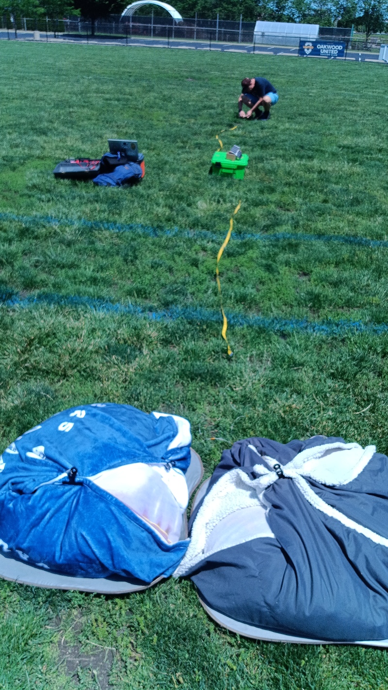
Smore-005 was similar to smore-003, with a goal of acheiving higher altitude. The balloons were pumped out with the pump in reverse to evacuate any air before filling with Helium. The launch went well, the balloon rose, but no telemetry was received. We heard confimation on the ground of transmit tones, but WSJT-X was not working properly to look for decodes.
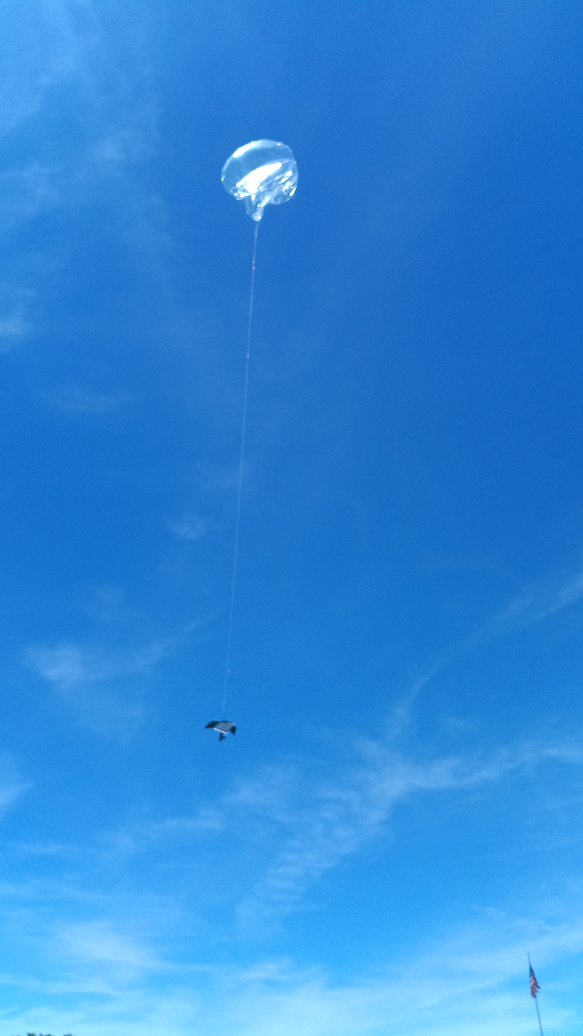
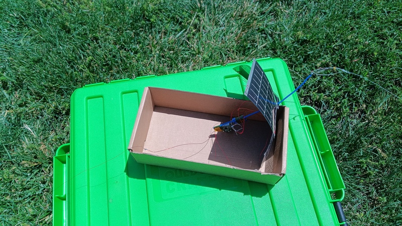
New payload design with 3 solar panels and zener diode.
Edited README on u4b to contain contact and WSPRtv tracking information in the unlikely event that someone can find it.
IF YOU ARE READING THIS:
BALLOON OPERATED UNDER CALLSIGN KF8EEZ. LAUNCHED FROM DAYTON, OHIO, USA.
TRACKING: HTTPS://WSPRTV.COM/?CS=KF8EEZ&CH=370&BAND=20M
EMAIL: PHONE:
half wavelength: 95.14683639918243 millimeters quarter wavelength: 47.57341819959122 millimeters quarter wavelength * 95%: 45.194747289611655 mm feed length: 25.400000000000002 mm total length: 70.59474728961166 mm
top and bottom arms from U4B about 5 inches. Antenna arms should be about 198.84837766362426 inches. I created two spools of 200 inch long each. For both, need to cut about 6.16 inches off of the spooled wire.
print(200 + 5 - 198.84) 6.159999999999997= 6.16 in
print(200 + 5 - 198.84) 6.159999999999997= 6.16 in
Twisted pair feed, 50mm arms. Tested. Good GPS fixes.
This is the primary program. The MYTELE and MYGPS subroutines enable control of a test mode which doesn’t need GPS or ability to transmit.
PRINT "START TRACKER2"
RUN "INIT"
RUN "SHOW"
LET B = 5
RUN "BLINK"
PRINT "INITIAL GPS"
RUN "MYGPS"
LET B = 2
RUN "BLINK"
10 PRINT "LOOP AT #VC"
RUN "SHOW"
RUN "MYTELE"
LET C = C + 1
IF C > N
    LET HP = 1
ENDIF
RUN "MYGPS"
GOTO 10Initialization should run once on power up.
This code should be edited for each flight. Specifically, set: - channel number: CH=xxx - test mode: T=1 for test without GPS/Telemetry OR T=0 for live
PRINT "INIT START"
LET CH = 370
LET HP = 0
LET C = 0
LET N = 2
LET T = 1
LET B = 5
PRINT "HOST USB:    #US"
PRINT "HIGH POWER:  #HP"
PRINT "FREQUENCY:   #FQ"
PRINT "CHANNEL:     #CH"
PRINT "CALLSIGN:    #CS"
PRINT "TEMPERATURE: #TK"
IF T = 1
PRINT "*** TEST MODE ***"
PRINT "FAKE GPS/TELE MODE"
ELSE
PRINT "REAL GPS/TELE MODE"
ENDIF
PRINT "INIT DONE"Prints out the current state
PRINT "SHOW START"
PRINT "LLH:  #LT #LN #AT"
PRINT "GPS:  VALID: #GV LOCK: #GL SPEED: #GS CALIB: #CL"
PRINT "GPS:  NSAT:  #SC"
PRINT "CNT:  #VC"
PRINT "TEMP: #TK"
PRINT "POWR: #HP"
PRINT "SHOW DONE"This is my GPS program, it lets you use the GPS in a test mode without an actual signal. Don’t acquire GPS if in test mode (T=1)
PRINT "GPS START"
RUN "LEDOFF"
IF T = 0
PRINT "REAL GPS"
GPS 360
ELSE
PRINT "FAKE GPS"
DELAY 2000
ENDIF
RUN "LEDON"
PRINT "GPS END"Don’t transmit if in test mode (T=1) This packs additional telemetry into the Z variable and sends a 3rd telemetry packet.
THESE URLs create the telemetry packet decode for WSPRtv.com: https://wsprtv.com/?cs=KF8EEZ&ch=216&band=20m&start_date=2026-05-17&ct_dec=ct,s:2_500:0:1,2:0:1,38:0:1,1000:t100,1000:t101&ct_labels=count,power,nsat&ct_llabels=spot+xmit+since+power,power,number+sats
https://wsprtv.com/tools/ct_wizard.html?spec=https%3A%2F%2Fwsprtv.com%3Fcs%3DKF8EEZ%26ch%3D216%26band%3D20m%26start_date%3D2026-05-17%26ct_dec%3Dct%2Cs%3A2_500%3A0%3A1%2C2%3A0%3A1%2C38%3A0%3A1%2C1000%3At100%2C1000%3At101%26ct_labels%3Dcount%2Cpower%2Cnsat%26ct_llabels%3Dspot%2Bxmit%2Bsince%2Bpower%2Cpower%2Cnumber%2Bsats
PRINT "TELEMETRY START"
RUN "LEDOFF"
LET Y = ERLAT 1000
LET X = ERLON 1000
LET Z = 0
LET Z = PACK Z 1000 Y
LET Z = PACK Z 1000 X
LET Z = PACK Z 38 SC
LET Z = PACK Z 2 HP
LET Z = PACK Z 500 C
IF T = 0
PRINT "REAL TELE"
TELE
TELEC Z
ELSE
PRINT "FAKE TELE"
DELAY 2000
ENDIF
RUN "LEDON"
PRINT "TELEMETRY END"Turn LED off
OUT 19 0Turn LED on
OUT 19 1turns led on and off B times. you must set b first
FOR L = 0 TO B
RUN "LEDON"
DELAY 100
RUN "LEDOFF"
DELAY 100
NEXT